FEDERAL AGENCY FOR EDUCATION GOU VPO
Department of MABN
COURSE WORK
in the discipline "Diagnostics of infantry fighting vehicles"
on the topic
:
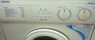
the SMA “Vyatka-Avtomat” automatic washing machine
Completed:
Art. gr. MZ-6
*****@***ru
Checked:
Associate Professor, Ph.D.
*****@***ru
Ufa-2006
Table of contents
1) Description of the automatic washing machine “Vyatka-
Automatic"…….……………………………………………………………3
2) Development of a structural and functional diagram of a washing machine .....13
3) Development of a functional model for two faults…………..15
4) Development of a fault finding matrix for the first fault...17
5) Development of a troubleshooting algorithm for the second fault
half-splitting method………………………………………..19
6) Development of a troubleshooting algorithm
washing machine………………………………………………………21
Description of the automatic washing machine " Vyatka-Avtomat "
Kishinevsky
The company was founded in 1944, and today it has a rich history. Initially, the plant produced small kitchen utensils. Later, serious electrical engineering began to be developed here.
The production of the Nistra washing machine was established in 1960. The AURICA washing machine was also assembled here, which was the first in the Soviet Union to receive a quality mark.
As the company grew, the range of products expanded. And if at first semi-automatic washing units were produced, then the cycle was reconfigured to fully automatic machines. We also managed to establish the production of other products, including sinks, gas stoves, kitchen blocks, waterers for calves, etc.
Today Kishinevsky is also functioning.
The processes of casting and pressing of plastics are established here. In addition, the company carries out galvanizing, chrome plating, powder painting and other operations.
Fig.1. Design of the Vyatka-Avtomat washing machine
| 1 – detergent dispenser | 2 – support |
| 3 – tank suspension spring | 4 – hose |
| 5 – solenoid valve | 6 – washing tank |
| 7 – pulley | 8 – inlet hose |
| 9 – thermostat sensor | 10 – electric heater |
| 11 – electric motor | 12 – drain hose |
| 13 – level sensor tube | 14 – shock absorber plate |
| 15 – capacitor | 16 – shock absorber spring |
| 17 – friction disc | 18 – electric pump |
| 19 – filter | 20 – drainage tube |
| 21 – level sensor | 22 – counterweight |
| 23 – command apparatus | 24 – indicator lamp |
| 25 – program switch | 26 – command device handle |
| 27 – front wall of the case | 28 – machine body |
| 29 – hatch cover | 30 – housing cover |
| 31 – dispenser box | 32 – inlet hose |
| 33 – solenoid valve |
The machine operates from a cold and hot water supply network and is designed for washing, rinsing and spinning items made from all types of fabrics. It has front loading of laundry. The machine provides a choice of washing modes with a set of specific programs using low-foaming synthetic detergents. Programs are recruiting
control handle of the command apparatus and special switches located on the front panel of the machine body. The machine is protected from water overflow and is equipped with a hydraulic filter that retains foreign bodies.
The connection between the filter cover and the housing is sealed and can withstand a pressure of 9.4 kPa. The design of the machine ensures complete drainage of liquid from the tank: the permissible remaining liquid in the hydraulic system is no more than 500 ml.
Regulation of programs and temperature of washing solutions when washing, rinsing and spinning products is carried out automatically. They only manually load the products and detergents, dial in the required program, turn off the machine and unload clean laundry.
The metal body of the machine 28 is made of sheet steel coated with white paint. The body consists of stamped parts connected by rivets and welding. The top of the case is closed with a metal cover 30, painted white and attached with self-tapping screws. Inside the housing there is a washing tank 6 with a two-speed electric motor 11 mounted on it to drive the washing tank. In the upper part of the housing there are: a connection block to the water supply network, consisting of two electromagnetic valves 5 and 33, connected by hoses 4 to a detergent dispenser 1, which provides the possibility of automatically introducing detergents, bluing and starching agents into the machine; capacitor 15 for the electric motor; liquid level sensor 21 connected to the bottom of the tank with a hose 13. On the upper part of the front wall 27 of the housing there is a push-button switch 25, which serves to select the economical washing and spinning mode; to the right of the switch there is a command device 23 and a neon lamp 24, signaling the operation of the electric motor. The control unit is covered with a plastic panel on which the handles 26 of the command device and the switch 25 are located; Here (on the left) there is a drawer 31 of the detergent dispenser and a panel with program inscriptions located under the handle of the dispenser drawer.
Washing tank 6 is made of carbon steel followed by hot enameling. The upper part of the washing tank is suspended from the machine body on two cylindrical springs 3. The springs are attached to the upper part of the body through supports 2. Metal springs are welded to the lower part of the washing tank on both sides: counterweights 22 made of concrete are mounted on the washing tank. A tubular electric heating and temperature sensor 9 are built inside the washing tank. A perforated washing drum with three ribs is installed in the washing tank. The axis of the washing drum is extended outside the latter through seals in a cast support attached to the rear wall of the washing tub. A pulley 7 is placed on the axle, connected by a V-belt to a pulley on the electric motor shaft. In the front wall of the washing tub there is a loading hole connected to the loading hatch using
fixed rubber cuff of special profile. This part of the machine contains a drain electric pump 18 and a removable filter 19, the cover of which is located on the lower part of the front panel of the housing. The machine is equipped with a removable water inlet hose 8 and a drain hose 12. The presence of a rectangular hole in the rear of the machine that can be closed with a lid and the ability to remove the top cover provide convenient access to the structural elements and instruments of the machine, which is of great importance when repairing it.
Service life and build quality
Thanks to the mass production (assembly) of SMAs in the Russian Federation, prices for washing machines uncontrollably crept down - they became available to the population. According to statistics, every fourth family has an automatic washing machine. If you believe the service centers, then it is the washing machines assembled on Russian territory that are very unreliable. Here is their anti-rating, they break down more often than others:
- Indesit;
- Bosch;
- Beko;
- Vestel;
- Candy.
Uptime rating:
- from the Chinese configuration - 2 years;
- from Italian, German, Korean - about 5 years.
For comparison, the service life of the original models assembled in the countries that own the brands:
- Korean - 8 years;
- German - 10–16 years;
- Swedish and Austrian - 14–20 years.
As you can see, the difference in service life is multiple. When buying a Russian-assembled SMA, you should know: it will last 3–4 times less than an analogue made in the country of origin. The main advantage of cars from Russia is their lower cost. It is important to know that Korean, German and other models of famous brands are also assembled in Slovenia, Poland, China and other countries. They are of lower quality than the originals, but still better than devices assembled in Russian factories.
Level sensor-relay RU-3SM
The RU-3SM level sensor-relay is used to control the specified level of water filling into the washing machine tank. The level sensor-relay is set to operate at pressure, Pa: 1765 – when the water level rises; 588 – when the water level drops. The operating range is when the level increases from 755 to 2450 Pa, the dead zone is at least 490 Pa. The electrical load on the contacts of the level relay switching device is no more than 16 A at a voltage of no more than 250 V AC, a frequency of 50 Hz and a power factor of no less than 0.8.
All main parts of the level switch are fixed to the housing (Fig. 2). A membrane is placed between housing 2 and the cover, which serves as a sensitive element and divides the level switch into two cavities. One cavity is sealed and is connected through fitting 3 to a controlled water level. The second cavity houses switches. Connected to the membrane is a rigid center with pushers, which, through stops 7, transmit force to the switching flat springs and to the adjustment springs 9. On the opposite side, the springs 9 rest against the adjusting screws 8. Instant transfer of contacts is carried out due to tilting springs.
Rice. 2 Schematic diagram of a level relay.
1 - rivet, 2 - body, 3 - fitting, 4 - membrane, 5 - cover, 6 - center with pushers, 7 - stop, 8 - adjusting screw, 9 - spring
The fixed contacts are attached to the body with 2 rivets 1. Adjustment of the response and dead zone, as well as the gaps between the contacts, is carried out with special screws. Adjustment to required levels
actuation is carried out by changing the compression of the adjustment spring with screws 8.
An additional protective contact is built into the level switch on the switching plates. The cover 5 of the membrane 4 is attached to the body 2 by rolling the edges of the cover onto the shoulder of the body. To eliminate the influence of pulsations of a controlled level on the response, a calibrated hole is made in fitting 3 for air throttling.
The operating principle of a water level switch (also called a pressure switch) is based on converting the pressure created by a column of liquid and acting on a membrane into the movement of movable contacts and switching of the contact devices of the level switch. When the pressure increases and the upper set value of the water level is reached, the membrane switches contacts through pushers. When the pressure decreases by the value of the dead zone, the contacts switch back. Instant transfer of contacts is carried out due to switching flat springs.
Depending on the design, the relay can be configured to several levels. In Fig. Figure 3 shows three states of the so-called two-level relay.
Rice. 3 Schematic diagram of a level relay.
a) both contacts (A and B) are open;
b) level I: contact A is closed, contact B is open;
c) level I: contacts A and B are closed.
When switching currents up to 16 A and voltage 220 V, it is possible to weld the contacts at the time of draining the water. In this case, to prevent the heating element from burning out, an additional contact is built into the level relay, which switches a current of 0.1 A at a voltage of 220 V and closes reliably when water is drained from the tank below a given level point. Through a protective contact, the power circuit of the electric valve is turned on to open the emergency water supply to the washing machine tank,
which protects the heating element from burning out, and if the water temperature in the tank rises to 60 C or higher, the power supply circuit of the heating element is de-energized using a temperature protection relay.
What is produced and assembled in Russia?
In the Russian Federation there are a lot of enterprises representing Italian, German, Korean and other foreign brands. The following brands of SMA are collected here:
- "Ariston" and "Indesit" (Italy) - they are made at the Lipetsk plant;
- LG and Samsung (Korea) - they are assembled in the Moscow and Kaluga regions, respectively.
- "Vestel" and "Beko" (Turkey) - assembly is carried out in Kirzhach and Aleksandrov (Vladimir region)
- Siemens and Bosch (Germany) - at enterprises in St. Petersburg.
- "Candy" (Italy) - on .
- "Atlant" (Belarus) - gathers in Moscow.
- "Rolsen" (South Korea).
- "Ocean". If you are interested in a Russian-made washing machine, take the product. It is located in the Far East (Primorsky Territory, Ussuriysk). "Ocean" produces SMA with both loading options - vertical and frontal.
- . Most Russian-made devices are activator. They are taken for summer cottages. They are compact, mobile, and inexpensive. An example of such equipment is the Sibir semi-automatic machine. They are produced in Omsk.
- Evgo. The location of the facilities is Khabarovsk. The filling in the cars is Chinese.
Command apparatus
The sequence and duration of performing specified laundry processing operations is carried out using a command device that has a system of contacts, the switching of which allows you to control the operation of the elements of the complex electrical circuit of the washing machine.
The command device (otherwise called a timer or programmer) is the main mechanism of the control system, which coordinates the operation of all executive bodies of the washing machine by closing and opening the contacts of the electrical circuit at specified intervals.
A cam-type command device (Fig. 4) consists of a stepper motor, a set of cams and contacts that close or open when the cams are turned. Using the handle, which is located on the control panel of the machine, the initial position of the cams is set in accordance with the selected program.
The control cams are divided into two groups:
-working (main) cams;
- auxiliary cams (they are also called high-speed or reversible).
The working cams control the washing machine's electric motor, drain pump, inlet solenoid valve and heating element. Auxiliary cams control changes in the direction of rotation of the drum during washing, as well as special washing and spinning programs (delicate modes).
Rice. 4 Cam-type command device:
1 - cams, 2 - electric motor, 3 - contacts, 4 - program dial, 5 - program selection handle
A group of working (main) cams is driven by an electric motor of the command device. The cams make discrete turns (steps), with a full 360° rotation of the cam typically taking 60 steps. Depending on the design of the control device, the time for a full revolution can be 90, 120 or even 300 minutes.
The operating cam is designed in such a way that the contact controlled by it can be in two or three positions. The two positions correspond to the states “closed” or “open”. The following states correspond to three positions:
- closing the contact between the common input and output A;
- circuit opening;
- closing the contact between the common input and output B.
The time the contacts remain in one position or another is determined by the profile of the cam. A graph reflecting the state of contacts at each step of program execution is called a cyclogram of the command device (Fig. 5).
To perform some special operations, the command device can be equipped with a system for stopping the advancement of the cams. This blockage may remain until the washing machine performs certain functions. The washing program continues after these functions have been completed.
For example, the “Thermostop” device is used to prevent the movement of the cams of the control device until the water in the tank reaches the desired temperature. It blocks the working cams in relation to the main axis of the command device, leaving only the auxiliary cams in operation.
Rice. 5 States of contacts at various steps of program execution (cyclogram of the command device)
Another locking operation, “Hydro Stop” (sometimes also called “Post Rinse Stop” or “Before Spin Stop”), consists of stopping the machine with laundry and a partially filled tub after a gentle rinse when washing delicate fabrics. To do this, the power supply to the electric motor of the control device is interrupted. The machine's operation is suspended until the user manually moves the control unit one step.
The main switch of the machine can also be built into the command apparatus; in this case, it can be turned on and off using the program selection handle, moving it along the axis of the command device (pushing it towards you or retracting it). The main contacts L and N of the washing machine power circuit are affected by a disk combined with a handle (Fig. 6).
Rice. 6 Closing the contacts of the main switch of the washing machine when the program selection handle is pulled out
What are the features?
AGRs produced and assembled in the Russian Federation are designed for our customers. And they are concerned about the following nuances:
- Loading is frontal. According to statistics, this is the option our compatriots prefer. Perhaps they are attracted by the design: the “vertical” models remind them too much of the regular activator versions.
- Compactness - dimensions should be reasonable. Many consumers are limited in space, so they prefer small-sized versions.
- The capacity of the drum is larger so that you can do a large wash and wash all the things at once.
In Europe today they prefer vertical loading, but since Russians choose the side option, most European brands focus on the production of “front-facing” models. Only Ariston offers several “vertical” modifications.
The dimensions of the models also meet the needs of Russians. Brands offer the following options:
- With reduced depth - 50–55 cm.
- Narrow - 39–49 cm.
- Super narrow - 33–36 cm.
Full-size versions are also available. They are produced only by LG, Kandy, Ariston.
Installation
Any of the above Vyatka Katyusha models comes with detailed operating instructions.
It is written in an accessible form and is accompanied by a number of visual diagrams. In order for the equipment to function correctly, it must be freed from its industrial packaging and fixing bolts. Vyatka automatic
The Vyatka Katyusha automatic washing machine is picky about its location. It must meet the following characteristics:
- Along the perimeter, be sure to maintain a distance of 1.5 cm from the device to the walls.
- It is important to adjust the legs from below so that the gap between the washing machine and the floor is at least 1 cm.
- It is important to level the device, ensuring a minimum tilt angle. Ideally, the Vyatka Katyusha machine should stand strictly horizontally, which will help avoid frequent repairs of worn parts.
- Nearby it is necessary to have communications from where the device draws water, a sewer outlet for draining waste liquid and a grounded socket. If the residential premises have old wiring, for such household appliances it is recommended to change it or make another branch from modern materials.
The manufacturer recommends placing the washing machine on a bare floor or an anti-vibration mat. The use of pile carpets is strictly prohibited.
After purchasing the equipment and transporting it to your home, you can start installing it. You should unpack the washing machine carefully; do not tear the box. After you have freed the unit from its packaging, you should remove the shipping elements from it. Their schematic location and removal instructions can be found in the image below. Items for transportation are required. They secure the drum, so it does not spin during transportation.
Do not throw away the transport bolts; they should be saved. For example, in case you move.
Preparing the site
You have unpacked the machine, and your next step is to move it to its designated place. This will be a permanent place where the washer will perform its duties. When choosing such a place, you need to meet several conditions:
- The floor under the machine must be strong and level.
- Remove carpet runners; you can only place a special rug under the machine.
- For maintenance, it is necessary to have nearby sewerage, water supply and an electrical outlet.
- The washing unit must be placed so that there is a gap of one and a half centimeters from the body. The distance from the floor to the bottom of the machine should be about 1 cm.
READ MORE: Canopy beds 77 photos white and black models for adults and girls interior ideas do it yourself step by step mounting options
Adjustment
After the location has been selected and prepared according to the rules, you can install the washing machine. It must be level. The maximum angle of inclination of the unit relative to the level is 2 degrees. The washing machine also has legs. By twisting them you can adjust the angle of inclination. By unscrewing the locknuts you can change the height of the legs.
Connection
The next step is to connect the washing machine. First, a connection is made with the water supply and sewerage systems. Only then can you turn on the machine to the network. Our model requires a grounded electrical outlet. It must be protected automatically. The socket is powered by copper or aluminum wires. It is advisable to call an electrician. If the outlet is ready, then insert the cord into it.
Where can an electric motor be used?
Craftsmen have come up with dozens of options for using a motor from an old washing machine. But they all have the same concept - using the engine torque to start the operation of additional mechanisms . The following options are considered the most popular homemade products.
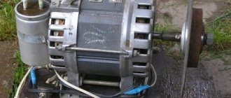
- Grinder. To do this, the motor is firmly fixed to a solid base and the grinding wheel is connected to the shaft. All that remains is to connect the washing machine motor to the network and you can start sharpening knives, axes, and scissors.
- Concrete mixer. Not only electricity is taken from old technology. the engine, but also the drum. With a little modification, you will get an excellent construction tool that will save a lot of money and time. Some craftsmen can even make a deep vibrator.
- Mill or crusher (feed cutter). This homemade product is suitable for people living in rural areas and raising livestock.
- Vibrating table Connecting an electric motor to the countertop will provide an inexpensive tool for making paving slabs or cinder blocks.
But before you start disassembling your washing machine, you should find out the type of electric motor you have. This will allow you to determine the scope of its application and the method of starting from the mains.
Connection rules
When the type of electric motor installed on the old washing machine has been determined, you can begin connecting.
Recommendations
Advice! If you plan to use a powerful modern motor, you should remember the following points: capacitors are not needed for their operation, and a starting winding is also not required.
Before connecting a device with more than 3 terminals to the network, you need to understand the colors of the wires coming out of the transfer case:
- often a white winding means that these wires belong to the tachogenerator; they will not be useful in the future;
- brown and red are connected to the stator winding and rotor;
- The gray and green wires are graphite brushes.
Although this recommendation applies to most models, there are some releases where the colors may vary. To be sure of your choice, you need to ring all pairs using a tester and a multimeter. Those that go to the tachogenerator have a resistance of 60-70 Ohms.
Important! After connecting all the wires of a modern 6-pin engine, you can check the functionality of the device by connecting it to a car battery. When voltage is applied through the starting relay, it will immediately (without acceleration) begin to rotate. If the test has confirmed the effectiveness of the circuit, you can connect the motor to a 220-volt network, having first firmly secured the motor.
Scheme
Old engines have 5 wires - one goes to ground. The rest can be easily divided into pairs by simply ringing them. Now it is important to determine which pair is related to start-up and which is working. Usually the resistance is higher at the starters, and it is they that need to be connected via a capacitor to the “SB” button. To prevent the engine from burning out, the button must be without a lock; for this purpose, you can use a doorbell. Sometimes such motors have three output wires, which means that the two windings were connected at the factory.
