The refrigerator does not turn on and you need to find out the cause of the breakdown? Are you choosing a new unit and want to understand the differences in the operating principle of different models? The electrical diagram of the refrigerator, which reflects the interaction of its main components, will help with this.
By understanding the operating principle, you can avoid being deceived by technicians or repair the refrigerator yourself, as well as reduce the risk of breakdowns and increase the working life of the device. In this article, we will look at diagrams of devices of various types: single-chamber and 2-3-chamber, with and without the NoFrost system, two-compressor, with mechanical and electronic control.
Malfunctions of the Indesit refrigerator and methods for eliminating them
Most Indesit refrigerators are two-chamber; using their examples, we will look at the malfunctions characteristic of these models. Signs of a malfunction of the Indesit refrigerator compressor are:
- the unit operates noisily, with uncharacteristic knocking and whistling;
- starts for a few seconds and stops;
- does not produce cold.
Replacing a compressor and filling the system with refrigerant is an expensive, complex repair. This is caused by prolonged operation of the device in conditions that do not meet operating requirements or depletion of the resource.
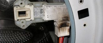
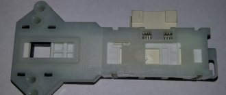
The most common and less costly reason will be the failure of the thermostat. The manufacturer has determined the working life of the thermostat to be 5 years. Signs of a malfunctioning thermostat:
- The temperature in one of the chambers does not hold.
- The compressor may not turn on, but may run continuously.
- The electromechanical thermostat does not make a characteristic click when the knob is turned to 0.
You can replace the temperature sensor yourself. The node is connected to the thermostat.
Why is the cooling mode not maintained in the chambers? If the compressor does not turn on, you need to check the contacts of the start-up relay. They may burn out or stick and will need to be replaced.
Long-term operation of the device is accompanied by gradual volatilization of freon. In case of mechanical damage to the evaporator, leakage due to corrosive wear at the junction of copper and aluminum tubes, in the door heating circuit, the gas quickly leaves the circuit. Lack of freon impairs the operation of the refrigerator. Heat dissipation is reduced. Signs will be an increase in temperature and the formation of a “fur coat” in the refrigerator. The circuit needs to be refilled with freon.
The refrigerator will operate with the same symptoms as a lack of freon if the capillary tube is clogged. The difference is determined by the temperature of the condenser and its heating zones.
A faulty board in an electronically controlled refrigerator paralyzes the operation of all systems. A breakdown occurs when there is a power surge in the network. To avoid problems, all devices with electronic control units must be connected through a voltage stabilizer.
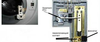
For Indesit refrigerators with No Frost, malfunctions related to fan operation and ice thawing are possible. The electronic display displays code F04. The fan may stop due to freezing of the blades or a malfunction in the electrical circuit. To defrost the internal ice behind the wall and in the chamber, dry it, and start the fan, it takes at least a day. Ice builds up on the propeller if the ice defrost heater on the evaporator is not working. It turns on at the command of the thermostat. There may be a malfunction of the heating element, wiring, or thermostat. Error code F7.
Each refrigerator model has features in its design, cooling circuit, electrical and electronic control circuits. Let's look at the malfunctions that are typical for different Indesit refrigerators, why they don't turn on and don't freeze.
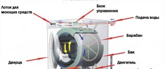
Refrigerator operation diagram
The refrigerator consists of:
- Compressor, which is of inverter and linear type. After starting, the compressor begins to drive freon through the system, thereby cooling the chambers;
- Condenser - tubes located on the back wall of the refrigerator body. Thanks to the condenser tubes, the refrigerator does not overheat;
- An evaporator in which freon boils and passes into a gaseous state;
- A valve for thermoregulation, which serves to maintain a given pressure;
- The refrigerant is freon gas or isobutane, which, circulating through the system, helps cool the entire chamber.
Image 1 – refrigerator operation diagram
The refrigeration system is closed. The compressor pumps refrigerant out of the evaporator, which in turn enters the condenser under high pressure. In the condenser, the gas is cooled and changes its state of aggregation from gaseous to liquid. The resulting liquid flows through the tubes into the evaporator. This ensures closed, continuous operation.
Almost all components of the refrigerator work non-stop. The compressor must be turned on by the signal from the temperature sensor at the moment when the permissible temperature sensor limit is exceeded. After the signal is given, the compressor, driven by the relay, begins to work intensively until the temperature indicators return to normal. Then the motor turns off again.
To replace the compressor with your own hands, you need to understand the electrical circuit.
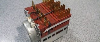
Image 2 – electrical diagram
Having the necessary knowledge and having the necessary tools at hand, you can easily determine the cause of the breakdown and fix it yourself.
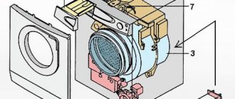
Image 3 – current flow diagram
According to the diagram, in operating condition the current travels the following path:
- First, the current passes through the contacts on the thermal relay (1);
- Then it hits the defrost button (2);
- Then it goes to the thermal relay (3);
- Next on the current path is the start-up relay (5);
- The working winding of the motor motor is at the end of the path (4.1).
If the winding is not working, it will pass a large voltage. The starting relay will operate, close the contacts and start the winding. As soon as the temperature reaches the desired value, the thermal relay contacts will open and the engine will stop.
Malfunctions of the refrigerator thermostat Indesit C132G016
The model is two-chamber, with 1 compressor, electromechanical control. Condensate is removed from the refrigeration chamber by drip; the freezer requires manual defrosting. The refrigerator is very reliable; during normal operation it operates without repair for more than 10 years.
A typical failure in the model is the failure of the thermostat. This is a housing part with internal relay contacts and a membrane. If the unit malfunctions, the refrigerator compartment does not work, and the temperature in the freezer drops. Due to the inability to analyze, the sensor sends incorrect commands to the module. The compressor may run without stopping, which will lead to its breakdown. The motor does not turn on if the sensor does not give a start command.
The thermostat cannot be repaired and must be replaced. To do this, disconnect the refrigerator from the network and replace the sensor according to the operating instructions. We suggest watching a video on replacing the thermostat on a refrigerator.
How to check the compressor for performance?
In order to determine whether the device is functioning or not, you need to prepare a tool - a multimeter. Before fixing the terminals of the device, you must make sure that the body of the device is not energized, otherwise the technician runs the risk of electric shock.
If everything is normal, then you will need to apply the terminals of the device to the contacts one by one. The device is considered working if “∞” is displayed on the screen. If an incomprehensible set of numbers is displayed, then there are winding faults.
In order to continue testing the equipment, it is necessary to dismantle the compressor. So that you can understand how to do this, let's look at the process in more detail.
Dismantling the compressor: step-by-step instructions
Step one: first you need to disconnect the conductors from the contacts.
Use wire cutters to disconnect the engine pipes.
Step two: now you need to unscrew the fasteners.
You will have to unscrew the screws to get the relay out.
Step three: next we need to determine the degree of contact resistance. The terminals of the device should be connected to the output contacts. If everything is normal, then the value should be 30-35 Ohms (this depends on the type of device). If a value is obtained that is not within the normal range, the component should be replaced.
If the value does not deviate from the norm, then test with a pressure gauge:
- Connect a hose with a branch to the blower.
- Turn on the engine.
- Check the pressure.
The process of measuring compressor pressure
If the compressor is working properly, the pressure will be within six atmospheres. Therefore, when testing, you should immediately turn off the pressure gauge. Otherwise, high pressure will cause it to break. If the compressor does not work, the pressure will remain within four atmospheres, so the component will need to be replaced.
If the pressure remains normal and the device does not function, then most likely the problem is a faulty start relay.
Replacing the compressor: step-by-step instructions
Replacing a compressor is a complex process that requires certain skills from the technician. However, if you decide to do it yourself, then you must follow the steps of the instructions.
Step one: you need to prepare the tools that will be needed for the job. This includes the following:
- oxygen-propane burner;
- pliers;
- freon storage;
- valve;
- portable refueling devices;
- pipe cutting device;
- clamps;
- a cylindrical device for high-quality connection of the device with the pipe during refueling;
- copper tube;
- filter for installation in a pipeline;
- refrigerant cylinder.
Tools that will be required during the work
Step two: next you need to release the refrigerant.
You can do this in the following way:
- Using pliers, pinch the tubes that connect to the cooling system. At the same time, such work should be done carefully, because if you saw off the tubes with force, dust will form, which can get into the condenser and damage the elements.
- Then turn on the refrigerator for five minutes. This time is enough for freon to condense.
- Then the hose that comes from the cylinder should be connected to the filling line.
- Then open the valve on the cylinder to collect the refrigerant. Typically this takes less than 60 seconds.
- Next, you need to disconnect the relay block with wiring (dark box).
- Leave the markings to install it correctly.
- Then, using pliers, you need to remove the clamps.
- Next, you need to disconnect the wiring that goes to the plug.
- Then you can unscrew the device.
- The tubes must now be cleaned before installing another device.
It is necessary to bleed off the freon.
Step three: now you should check the degree of resistance again. You will need an ohmmeter here. As in the previous case, it is necessary to alternately apply the terminals of the device to the contacts. The resulting values must be checked against the nominal values for the specific device.
If the measurement is made with a charging device, then the following manipulations must be performed:
- Attach the negative terminals to the 5 V lamp body.
- Secure the positive terminals to the winding from above.
- Touch the ends of the winding one by one with the base.
If the device is working, the light should light up when touched.
Measuring resistance
Step four: now you need to measure the current. First, the device checks the start relay connected to the engine. After which the terminal must be connected to the device. The obtained values must correspond to the motor power. If its power is 130 V, then the current will be 1.3 A.
Measuring device
Step five: installing a new compressor. The first step is to fix the new device on the crossbar of the refrigeration unit. You will have to remove the plugs from the tubes to complete the installation. Next you have to measure the pressure.
It should be remembered that the seal of the device should be broken (remove the tube plugs) no earlier than five minutes before installation. After which you will need to join the tubes using a torch. At the time of soldering, you should observe the direction of the fire from the burner - it should be directed to the inside of the tubes. Otherwise, this will lead to melting of plastic parts.
First, attach the filling pipe, then to remove the refrigerant, and lastly, the discharge pipe.
The process of connecting tubes using a torch
Step six: upon completion of installation, it is necessary to charge the equipment with refrigerant. First you need to connect the device to the filling line using a locking coupling. Then all that remains is to connect the contacts and install the protection relay.
After turning on the unit, it is necessary to fill the system with refrigerant by 45%. Then you should check the reliability of the connections and disconnect from the network. Next, you need to achieve the optimal pressure of 10 Pa, turn on the refrigerator again and fill it with freon. Finally, all that remains is to remove the coupling and solder the pipe.
Refueling process
Malfunctions of the refrigerator Indesit C138NFG
Two-chamber combined refrigerator with one compressor and electromechanical control. The No Frost defrosting system is used in the freezer and a “crying” wall in the cold chamber.
The temperature control in the chambers is independent, thanks to the presence of a magnetic valve on the refrigerant line between the freezer and the refrigerator. Faulty components of the Indesit refrigerator of this model, when the temperature in the chambers is not maintained, can be:
- freezer thermostat, if the required minus is not reached in the freezer;
- upper chamber thermostat, if the temperature in the refrigerator is incorrect;
- sticking of the switching magnetic valve;
- Freon leak or compressor failure.
Elimination of the causes is possible after a complete diagnosis by service center specialists.
The condensate drainage system in the refrigerator may become clogged. Failure of heaters in the No-growth freezer system will result in icing. The fan will stop, clogged with ice. A non-working defrost timer will also lead to such consequences.
A specialist can find and fix the problem, but before doing this, you should defrost the lower chamber for 24 hours. During this time, the refrigerator blades will be freed, and it will be possible to check whether the No Frost electrical network is working properly.
Connecting a compressor without a switch
Connecting a compressor to a system without a relay is carried out according to the diagram that we have given below.
Motor connection diagram without relay
You need to take a conductor with two wires on one side and a plug on the other side. One contact should be connected to the main point, and the other to the working winding. Now these contacts should be connected and the plug plugged into the socket. In this case, a working refrigerator will function.
Video - Connecting a compressor without a switch
Malfunctions of Indesit BIA 181 NF
The refrigerator is a two-chamber refrigerator with a bottom freezer and has energy efficiency class A. The device has one compressor with full No Frost in the chambers. On the forums, the model is described as reliable; malfunctions do occur, but the technicians advise you to pay close attention to maintenance.
A model with an external condenser mounted in the form of a grid above the motor will last longer if the heat exchanger is thoroughly cleaned of dust and pet hair once a year.
If the Indesit refrigerator does not freeze, malfunctions may be detected:
- network damage or lack of power.
- thermostat malfunction;
- Freon leakage due to the appearance of fistulas in evaporators or refrigerant pipes;
- plug in the capillary system.
- failure of the motor-compressor.
The No Frost system in both chambers is located behind the wall of the refrigerator. Products are cooled by air flow, condensate is deposited inside the system. The main sign of a malfunction of the Indesit air-cooled refrigerator is the appearance of ice inside the chamber and an increase in temperature due to a violation of heat transfer.
After completely defrosting the chamber with the fan not working, it becomes clear:
- defrost timer failed;
- break in the heater power supply circuit;
- The fan is broken.
If puddles form under the refrigerator, you need to check the integrity and serviceability of the condensate drainage system into the container installed on the compressor.
The appearance of frost in the refrigerator while the fan is running indicates a violation of the seal of the chamber. It is necessary to check the fit of the seal and its integrity. Adjust or eliminate door sagging. Choose a more correct operating mode. Optimally, select the middle setting.
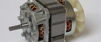
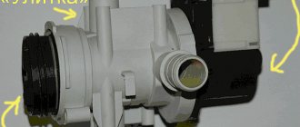
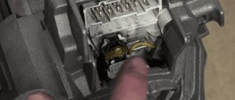
Refrigerator piston compressor design
This device is an electric motor with a vertical shaft; the structure is housed in a sealed metal casing.
External view of a piston compressor with the top casing removed
When the power is turned on by the starting relay, the motor drives the crankshaft, due to which the piston attached to it begins to reciprocate. As a result, freon vapor is pumped out of the evaporative radiator and refrigerant is pumped into the condenser. This process is facilitated by a valve system that opens and closes when pressure changes. The main elements of the piston design are presented below.
Design of a piston compressor in diagrammatic form
Designations:
- The lower part of the metal casing.
- Mounting the stator of an electric motor.
- Motor stator.
- Internal motor housing.
- Cylinder fastening.
- Cylinder cover.
- Valve mounting plate.
- Cylinder body.
- Piston element.
- Shaft with crank pin.
- Backstage.
- Rocker mechanism slider.
- Coil coiled copper tube for refrigerant injection.
- Upper part of the sealed casing.
- Shaft.
- Suspension mount.
- Spring.
- Suspension bracket.
- Bearings mounted on a shaft.
- Electric motor anchor.
Depending on the design of the piston system, these devices are divided into two types:
- Crank-rod. They are used to cool large-volume chambers because they can withstand significant loads.
- Crank and rocker. They are used in two-chamber refrigerators, where two units work together (for the freezer and the main container).
In later models, the piston is driven not by an electric motor, but by a coil. This implementation option is more reliable due to the absence of mechanical transmission, and is economical because it consumes less electricity.
Refrigerator Indesit NBA18FNF – main faults
The refrigerator is two-chamber, with a bottom-mounted small freezer of 63 liters, energy efficiency class B. The chambers use No Frost defrosting.
The main cause of malfunction of the Indesit refrigerator of this model will be the failure of the thermostat, a device that ensures the maintenance of the set temperature in the cabinets. Signs of a malfunction are:
- the refrigerator does not turn on, but there is light inside;
- the compressor runs continuously;
- in the cold chamber there is sub-zero temperature;
- The compressor stopped freezing.
How to check the performance of the compressor, find the one you need for your freezer and refrigerator, and change it yourself; step-by-step instructions are provided in the video.
However, the master can find other reasons. These include a lack or absence of freon, clogging of the capillary tube with refrigerant breakdown products in reaction with oil, and compressor malfunction.
Refrigerator Indesit B16FNF – faults and their elimination
Giugiaro series refrigerator with bottom-mounted freezer. The device has electronic control. No Frost is used in both departments. There is a freshness zone. Adjust camera modes on the front panel at the same time. There is an indication of operating parameters and a signal in case of deviations or violation of the tightness of the circuit. The energy efficiency of the equipment is class B. The main malfunctions of the Indesit refrigerator of this model relate to the control system and the cooling circuit.
In a refrigerator, the electronic control system may fail due to power surges in the network. Therefore, the device must be connected through a stabilizer. The problem point is the full No Frost system. Most often you have to change the fan or the power supply to it. If water is leaking from under the refrigerator, you need to inspect the condensate removal system.
Malfunctions of the refrigerator Indesit C132G
Freestanding refrigerator with electromechanical control. Manual defrosting is used for the freezer and drip defrosting for the refrigerator. The compact device is 167 cm high and has a volume of 241 liters.
The main malfunction of the Indesit refrigerator is that when the refrigerator compartment does not maintain the temperature, the lower cabinet does not freeze. There are several reasons, the main ones include:
- malfunction of the thermostat in the upper chamber and the thermostat in the lower chamber;
- absence or lack of freon due to a leak in the circuit or damage to the evaporators;
- plugs in the capillary system;
- failure of the motor-compressor or start relay.
But first of all, when you detect melted food, you need to check whether there is voltage in the power line and whether the power-on indicator on the refrigerator is on.
How to connect without a capacitor
The classic condenser in refrigeration equipment is used to cool and convert gaseous refrigerant into the liquid phase. The refrigerant pump allows short-term operation without a condensing unit, but long-term operation of the unit is not recommended (due to lack of oil supply). There is an electrolytic capacitor in the compressor itself, which provides an additional current pulse at the moment the equipment starts up. The capacitor was used in refrigerators produced in the 60s and 70s. last century.
The capacitor works in conjunction with the control relay and is placed in the gap between the power line and the starting winding. When checking the performance of the motor, you can connect the power directly, bypassing additional circuit components. In equipment manufactured after the 90s, the element is not used. The capacitor is used to start 3-phase electric motors connected to a household AC network. The installed element simulates the missing phase, but such motors are not used in household refrigeration equipment.
If there was a capacitor in the circuit, then it is removed (soldered off), and subsequent start-up is carried out through a standard relay.
If the motor does not respond to power supply, then you will need to remove the relay. If, when power is applied, a monotonous hum is heard from the compressor housing, then the cause of the breakdown is jammed rolling bearings or a broken piston pump. If the motor does not work and there is no extraneous hum, then the cause of the loss of performance should be sought in a broken wire inside the compressor. Such a unit cannot be repaired, but must be disposed of.