Innovative automatic washing machines make housekeeping much easier. If previously housewives spent several hours washing clothes, today electronic units have taken over this function. To extend the service life and to understand the operating principle of the washing structure, it is recommended that you familiarize yourself with the electrical plan.
Washing machine components
About the mechanism as a whole
Modern versions of Indesit, Samsung, Ariston are equipped not only with mechanical systems, but also with electronic programs that ensure reliable operation of the device. Moreover, normal functioning is ensured in different operating modes. For example, a temperature sensor is designed to operate in the range from +50C to +10000C. As the temperature changes, the resistance also changes.
On average, the power of the heating part of a Zanussi, Bosch maxx 5, LG WD, Ardo washing machine is 2 kW, resistance is 25 Ohms. The heating parts are made of metal tubes, which are equipped inside with fusible metal safety elements. The tubes are connected to a special relay. This is shown in the circuit diagram of the washing unit. In the event of an unusual situation, the relay is activated and the heating part is turned off. If the fuse has melted, it is replaced.
Main machine parts
The automatic machine diagram for Samsung, Zanussi, Bosch maxx 5, LG WD, Ardo necessarily includes a reliable leakage protection system that blocks the door. Additionally, the protective system includes an electronic valve through which all cold and hot water passes. How full the drum is is determined by the electronics in accordance with the program stored in the memory.
The progress of filling the loading tank with water is carried out gradually and is also regulated electronically. According to the principle diagram, a valve opens for the passage of water, which remains in this position for a precisely specified period of time. During the designated period, the laundry in the tank is saturated with water. The valve closes, the laundry is mixed and, if necessary, opens again for a few minutes to add water.
Appearance of a Samsung washing machine
How does a Samsung automatic machine work?
Samsung's latest technologies, which are used in the production of automatic washing machines (AWA), make them complex mechanisms. However, upon closer examination, the design of the unit is not difficult to understand.
The body of any model consists of:
- front panel,
- back wall,
- bottom and lid.
The external and internal parts of the unit are located according to the following diagram:
- On the front side there is a control panel, a powder tray, a drain pump, a hose, and a filter.
- On the top panel there is an inlet valve, a level switch, tank suspensions in the form of springs, and counterweights.
- On the front side there is a tank and shock absorbers.
- On the back surface there is a drive belt, motor, pulley, power cord, drain hose.
The internal filling of a technical product includes basic and additional devices. The main ones are:
- control module;
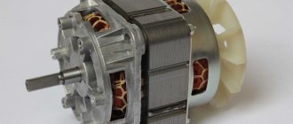
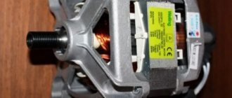
- electric motor;
- tank;
- heating element;
- electric pump
Each large and small part plays a specific role during operation of the machine, and its breakdown entails a deterioration in the quality of washing or a complete blockage of the equipment.
Control module
This unit in the washing appliance is the main electronic part. The control module is a kind of “brain” of the automatic machine ; it includes an indicator panel and the software module itself.
The power unit provides power and control of all functions performed. This is possible due to the connection of all sensors, electronics and actuators to the control module. If defects occur in the machine, a signal is sent to the electronic board and reflected on the panel in the form of blinking indicators or a code on the display.
The electronic board is very susceptible to voltage surges , so for flawless operation of the washing machine you need a device that protects it from voltage surges.
Motor and tachogenerator
These two important components in a washing machine function in pairs. The electric motor provides the drum rotation specified by the mode.
Most Samsung models are inverter-type machines with direct drive. In them, the motor is fixed on the drum from the rear panel. This feature increases engine efficiency and reduces the risk of breakdown.
The commutator type motor is localized in the lower part of the MCA . It manipulates the drum through a special belt that is attached to the motor shaft and drum pulley. This design leads to periodic wear of the electric brushes and the need for more frequent repairs.
The tachometer monitors the number of revolutions. The tachogenerator sends the result of its tracking to the control module, which checks the speed according to a given program.
Level sensor and filling valve
These details also work in synergy. The purpose of the pressure switch is to control the volume of water poured into the tank . Externally, this element is a round box with wires, fixed under the cover of the machine body.
The level sensor detects the pressure in the tank and sends information to the control module. The latter, upon receiving a sign of a sufficient amount of liquid, sends an order to the filling valve to stop drawing water.
The valve responsible for the flow of water from the water pipe has one, two or three coils . The voltage that is supplied to them after a corresponding signal from the control module causes the membrane in the inlet valve to open. When the voltage drops, the diaphragm valve closes and blocks the flow of water.
Tank and drum
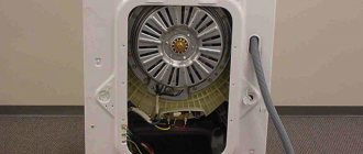
The washing machine tank is a sealed plastic container that is filled with water. Inside it there is a metal drum into which the laundry is placed.
This part of the unit has special devices to improve the quality of washing:
- grooved protrusions;
- plastic rib punches;
- perforations in the walls.
The maximum loading volume of the machine depends on the size of the drum.
This parameter differs in different Samsung models. The rotation of the drum is carried out due to a bearing built into the tank and a fixed shaft and transmission pulley.
The shape of the drum depends on the type of load. SMAs with vertical supply of laundry have a drum of a closed design. It is equipped with a door through which things are stored.
Heating element and temperature sensor
The heating element (heating element) is located at the bottom of the machine under the tank . This part ensures that the water is heated during washing to a predetermined temperature. The heating element receives a command about the required temperature level from the control module, after which it starts working.
Heating is controlled by a temperature sensor (thermostat or thermistor), which is built into the housing of the heating element. Outwardly, it looks like a metal tube. When the required temperature level is reached, the temperature sensor sends a signal to the control unit, which in turn turns off the heating element.
Thermostats are built into older Samsung models. In bimetallic products, the plate, in contact with the liquid, bends according to the temperature. As a result, the relay closes.
Gas-filled thermostats are connected via a tube to the control panel temperature sensor. The contacts close as a result of the expansion of heated freon inside the tube.
The second type of temperature sensors - thermistors , work by measuring resistance while heating water. These devices are considered more advanced and reliable. They are used in the assembly of technologically advanced modern Samsung models.
Springs, shock absorbers and counterweights
These design elements are designed to neutralize vibration and “bouncing” of the washing unit during spinning. Vibration dampers consist of a piston and a tube. These parts are attached to the side wall of the housing and the bottom of the tank.
Springs hang from the top and keep the tank suspended . The service life of the bearing and belt depends on the quality and condition of the shock absorbers.
Counterweights (or weights in other words) are concrete or plastic stones located at the bottom of the rear panel of the machine. They keep the tank balanced. Despite their massiveness and integrity, these parts can also be damaged during operation.
The cause of failure is often a crack in the counterweights or loose bolts . In the latter case, the rattling of the device is eliminated by tightening the fasteners.
Locking device and cuff
The mechanism that holds the door closed is essentially an electronic lock. The hatch is first closed mechanically by clicking the lock. After activating the specified program, the door electronically locks, which is accompanied by a soft click.
The hatch locking device guarantees accidental opening of the door during operation of the SMA . Unlocking occurs after the completion of the program upon receipt of the corresponding command from the control module.
The cuff also plays a protective role against possible leaks through the gap between the hatch door and the tank. Externally, it looks like a rubber seal. This accessory part must always be in satisfactory condition: clean, dry, without cracks or other damage.
Pump, snail, filter
A pump is provided to pump dirty water out of the tank after washing or rinsing. There are two types of application in Samsung washing machines: synchronous and asynchronous.
There are two main elements in the design of any pump:
- Motor
- Impeller.
A so-called snail is attached to the top (or front) part of the pump. It is necessary to connect the drain hose.
The same part contains a filter that filters out debris. The pump blades, mounted perpendicularly to its axis, begin to move when the rotor starts.
When waste fluid is discharged, small objects remaining in clothing (paper clips, coins, buttons) may enter the pump, filter and hose. This leads to pump failure and the need for repair.
To avoid problems with the operation of the machine, it is recommended to carry out preventive cleaning of the filter more often.
Hoses, pipes
These parts are designed to fill the tank with water and drain the waste liquid. The length of the hoses depends on the location of the machine and its distance from the sewer and water pipes. If it is necessary to reinstall the machine at a distant distance, use longer tubes.
The hoses are located outside the housing, while the pipes are located inside . The inlet and drain pipes work harmoniously and ensure unhindered flow of water.
New hoses and pipes are elastic and flexible. The appearance of cracks, deformations, and drying out threatens leaks, so failed main elements must be replaced in a timely manner.
Powder receiver
The dispenser is a container with different compartments for powder and conditioner . Detergents are loaded into the powder receptacle before starting the program and stored there until the desired washing phase begins.
After the soaking or washing mode is turned on, water enters the compartment with the powder and washes it into the tank. When the final rinse stage is initiated, water is poured through the conditioner compartment.
After each wash, it is recommended to dry the powder receptacle to avoid the appearance of a musty smell and mold.
About the circuit diagram
The electrical circuit diagram of the Ariston washing machine shows the exact connection between all the elements included in this circuit. Not everyone knows what a circuit diagram is and how it differs from a printed circuit board. In fact, this is a graphic display on paper, necessary to convey the connection between key elements, using conventional graphic, alphanumeric characters. The schematic diagram does not show the relative placement of the elements. The conclusions of the present elements and the ways of their connection with other elements are indicated here.
Electrical circuit of the Ariston washing machine
Other body parts
The main part of the design of an automatic washing machine has been described above. But there were some elements that were not mentioned:
- shock absorption system;
- powder hopper;
- washing machine body;
- hoses.
Depreciation
When rotating, the centrifuge causes strong vibration, so a rigid mount to the washing machine body is not used. The role of shock absorbers was taken on by special springs located around the perimeter of the drum.
Moreover, almost all models are equipped with a counterweight system. These are weighted blocks, each containing concrete or demagnetized metal. A well-designed shock-absorbing tandem makes it possible to almost completely eliminate body vibration. But this approach can only be seen on premium washing machines.
Washing machine counterweight
Powder hopper
The dispenser compartment contains a tray for powder and rinse aid. This compartment is connected to pipes through which water is supplied to flush out detergents.
The design of the Zanussi automatic washing machine differs from other models in the presence of the Jet System, which, thanks to the constant circulation of the washing solution, evenly saturates the laundry during soaking. The unit is able to determine the moment when the fabrics are well saturated and it’s time to turn off the water supply.
SMA Corps
If you remove all the internal parts from the machine, you will be left with a body containing a loading hatch and a top cover. The body is the frame of the machine to which all the elements and components of the washing unit are attached.
Hoses
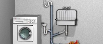
To fill or drain water from the machine, hoses are connected to it. The drain is discharged into the sewer or into a special container. The filler is connected at one end to the water supply and the other to the SMA.
Electrical connection
Not a single washing machine, be it Fairy, Bosch maxx 5, LG WD or any other, will function without being connected to the mains. The electrical circuit of modern washing units includes a three-core cord and a special plug with three stripes. Given this feature, the network cable must have a suitable cross-section and comply with the technical data. To ensure normal functioning of washing units, it is recommended to replace the wiring with a new cable.
General connection diagram for a washing machine
"EXPLOSION DIAGRAM" of a washing machine.
| 1 cover | 21 bolts |
| 2 building | 22 hatch hinge |
| 3 drawer hinge | 23 screw |
| 4 control panel | 24 drain hose clamp |
| 5 control panel wiring | 25 plug |
| 6 control board for | 26 back cover |
| 7 silicone buttons | 27 plug |
| 8 set of buttons | 28 hatch hinge plate |
| 9 disc time relay | 29 fixing screw |
| 10 timer knob | 30 insulation plate |
| 11 adjustment knobs | 31 side insulation |
| 12 hatch assembly | 32 plate |
| 13 hatch handle | 33 magnetic stop kit |
| 14 gasket | 34 magnet |
| 15 door hinge | 35 magnet support |
| 16 loop bases | 36 magnet adjusting washer |
| 17 hatch hinge gasket | 37 ring |
| 18 hinge support | 38 bar |
| 19 leg | 39 hose holder |
| 20 set stand | 40 plug |
About the conventions
Any circuit diagram by default includes symbols. In order for the average user to understand what information is displayed in this figure, it is recommended that you familiarize yourself with the main symbols and their encryption:
- ASQ is the system electromagnetic mechanism of the Aquastop function.
- BF - contact parts of the heating element, cooler or terminal block.
- VR – loading hatch lock.
- C – capacitor mechanism.
- EF/CL – rinse water supply mechanism.
- EF/L – water supply for washing.
- FRT is a heating element equipped with a fuse.
- LS – indicator light.
- M – grounding.
Main machine parts
Of course, the full list of symbols includes many more symbols. The user can familiarize themselves with the list in the instructions that come with each washing machine model.
"EXPLOSION DIAGRAM" of the tank/drum.
| 1 pulley screw | 19 drain pipe clamp |
| 2 bearing | 20 drain pipe |
| 3 screw securing the crosspiece | 21 seal ring |
| 4 bearing | 22 large drain pipe clamp |
| 5 oil seal | 23 shock absorber nut |
| 6 rear cross member | 24 nut M8 shock absorber |
| 7 counterweight mounting screw | 25 tank holder |
| 8 counterweight | 26 shock absorber |
| 9 tank mounting strip | 27 drum rib |
| 10 front cross member | 28 tank complete with drum |
| 11 bolt | 29 friction washer |
| 12 spring gasket | 30 axle bushing |
| 13 spring | 31 filler pipe |
| 14 gasket | 32 tank cross |
| 15 cuffs, hatch gasket | 33 pulley stabilizer |
| 16 outer hatch cuff clamp | 34 transmission belt |
| 17 clamp inner cuff of the hatch | 35 mounting bolt |
| 18 front counterweight | 36 weight counterweight |
